라즈베리파이 - 스텝모터 조작
https://blog.naver.com/elepartsblog/221510191478
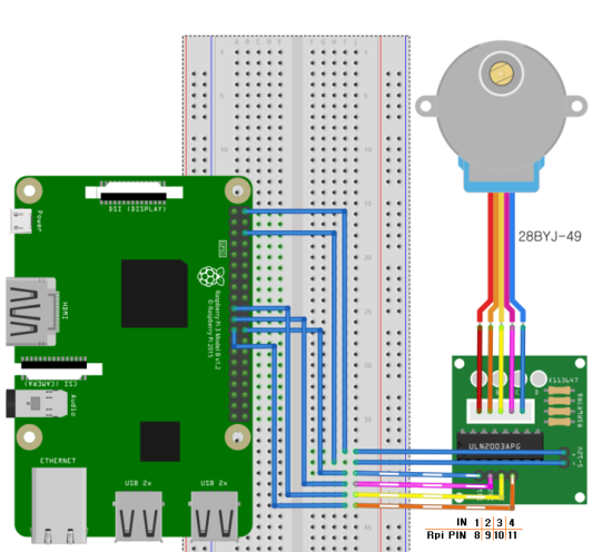
라즈베리파이 고급 키트 - 스텝 모터
안녕하세요. 오늘은 스텝 모터를 제어하는 실습을 해보겠습니다. 제품 구매 ↓↓ https://eleparts.co...
blog.naver.com
import time
import RPi.GPIO as GPIO

GPIO.setmode(GPIO.BCM)
StepPins = [8, 9, 10, 11]

# 핀 출력 설정
for pin in StepPins:
    GPIO.setup(pin, GPIO.OUT)
    GPIO.output(pin, False)

StepCounter = 0  # 스텝 수 세는 변수

# 싱글 코일 여자 방식 시퀀스
StepCount = 4
Seq = [
    [0, 0, 0, 1],
    [0, 0, 1, 0],
    [0, 1, 0, 0],
    [1, 0, 0, 0]
]

try:
    while 1:  # 무한 반복
        for pin in range(0, 4):
            xpin = StepPins[pin]
            if Seq[StepCounter][pin] != 0:  # Seq[][]가 0이 아니면 동작
                GPIO.output(xpin, True)
            else:
                GPIO.output(xpin, False)
        StepCounter += 1  # 1 증가

        # 시퀀스가 끝나면 다시 시작
        if StepCounter == StepCount:
            StepCounter = 0
        if StepCounter < 0:
            StepCounter = StepCount

        # 다음 동작 기다리기
        time.sleep(0.01)

except KeyboardInterrupt:  # Ctrl+C => 종료
    GPIO.cleanup()
ESP32 - 스텝모터 제어
[기본 제어]
https://stemwith.github.io/2021/09/25/ESP32-%EC%8A%A4%ED%85%9D%EB%AA%A8%ED%84%B0-%EC%A0%9C%EC%96%B4/
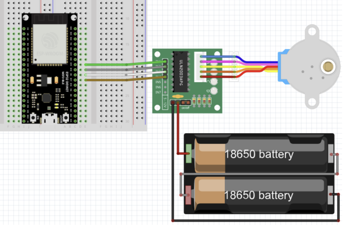
ESP32, 스텝모터
스텝 모터, 28BYJ-48Specification 정격전압: 5VDC 기어비: 1/64$$\frac {32}{9} \times \frac {22}{11} \times \frac {26}{9} \times \frac {31}{10} = 63.68395 \fallingdotseq 64$$ 스트라이드 각도 스펙상 5.625º &
stemwith.github.io
#include <Stepper.h>

const int stepsPerRevolution = 2048;  // change this to fit the number of steps per revolution

// ULN2003 Motor Driver Pins
#define IN1 19
#define IN2 18
#define IN3 5
#define IN4 17

// initialize the stepper library
Stepper myStepper(stepsPerRevolution, IN1, IN3, IN2, IN4);

void setup() {
  // set the speed at 5 rpm
  myStepper.setSpeed(5);
  // initialize the serial port
  Serial.begin(115200);
}

void loop() {
  // step one revolution in one direction:
  Serial.println("clockwise");
  myStepper.step(stepsPerRevolution);
  delay(1000);

  // step one revolution in the other direction:
  Serial.println("counterclockwise");
  myStepper.step(-stepsPerRevolution);
  delay(1000);
}
[웹 제어]
https://www.electronicwings.com/esp32/stepper-motor-interfacing-with-esp32
Stepper Motor Interfacing with ESP32 | ESP32
In this guide, we will learn how to Interface the Stepper Motor with ESP32 and control the direction of the Stepper Motor using the Web Server. Here, we are using a ULN2003 driver which is used to drive a stepper motor.
www.electronicwings.com
#include <WiFi.h>
#include <Stepper.h>

const char* ssid = "MULTI_GUEST";         /*Enter Your SSID*/
const char* password = "guest1357"; /*Enter Your Password*/

WiFiServer server(80); /* Instance of WiFiServer with port number 80 */
String request;

// Stepper Motor Settings
const int stepsPerRevolution = 200;  // change this to fit the number of steps per revolution
#define IN1 19
#define IN2 18
#define IN3 5
#define IN4 17
Stepper myStepper(stepsPerRevolution, IN1, IN3, IN2, IN4);
int Motor_Status;
WiFiClient client;

void setup() {
  Serial.begin(115200);
  /* Set the speed at 60 rpm: */
  myStepper.setSpeed(60);
  Serial.print("Connecting to: ");
  Serial.println(ssid);
  WiFi.mode(WIFI_STA);
  WiFi.begin(ssid, password);
  while(WiFi.status() != WL_CONNECTED)
  {
    Serial.print(".");
    delay(100);
  }
  Serial.print("\n");
  Serial.print("Connected to Wi-Fi ");
  Serial.println(WiFi.SSID());
  delay(1000);
  server.begin(); /* Start the HTTP web Server */
  Serial.print("Connect to IP Address: ");
  Serial.print("http://");
  Serial.println(WiFi.localIP());
//Serial.print("\n");
}

void html (){
  client.println("HTTP/1.1 200 OK");
  client.println("Content-Type: text/html");
  client.println("Connection: close");
  client.println();

  client.println("<!DOCTYPE HTML>");
  client.println("<html>");

  client.println("<head>");
    client.println("<meta name=\"viewport\" content=\"width=device-width, initial-scale=1\">");
    client.println("<link rel=\"icon\" href=\"data:,\">");
    client.println("<style>");
      client.println("html { font-family: Roboto; display: inline-block; margin: 0px auto; text-align: center;}");
      client.println(".button {background-color: #4CAF50; border: none; color: white; padding: 15px 32px; text-align: center; text-decoration: none; display: inline-block; font-size: 16px; margin: 4px 2px; cursor: pointer;");
      client.println("text-decoration: none; font-size: 25px; margin: 2px; cursor: pointer;}");
      client.println(".button_ON {background-color: white; color: black; border: 2px solid #4CAF50;}");
      client.println(".button_OFF {background-color: white; color: black; border: 2px solid #f44336;}");
    client.println("</style>");
  client.println("</head>");
  client.println("<body>");
  client.println("<h2>Stepper Motor Control using ESP32</h2>");
  client.println("<p>Click to Forward and Reverse the Stepper Motor</p>");

  if(Motor_Status == LOW)
  {
    client.print("<p><a href=\"/For\n\"><button class=\"button button_ON\">Forward</button></a></p>");
  }

  else
  {
    client.print("<p><a href=\"/Rev\n\"><button class=\"button button_OFF\">Reverse</button></a></p>");
  }

  client.println("</body>");
  client.println("</html>");
}

void loop(){
  client = server.available();
  if(!client)
  {
    return;
  }

  while (client.connected())
  {
    if (client.available())
    {
      char c = client.read();
      request += c;

      if (c == '\n')
      {
        if (request.indexOf("GET /For") != -1)
        {
          Serial.println("clockwise");
          myStepper.step(stepsPerRevolution);
          Motor_Status = HIGH;
          delay(500);
        }

        if (request.indexOf("GET /Rev") != -1)
        {
          Serial.println("counterclockwise");
          myStepper.step(-stepsPerRevolution);
          Motor_Status = LOW;
          delay(500);
        }
        html();
        break;
    }
    }
  }

  delay(1);
  request="";
  client.stop();
}
[수동 제어]
#include <Stepper.h>

const int stepsPerRevolution = 128;  // Change this to fit the number of steps per revolution

// ULN2003 Motor Driver Pins
#define IN1 19
#define IN2 18
#define IN3 5
#define IN4 17

// Initialize the stepper library
Stepper myStepper(stepsPerRevolution, IN1, IN3, IN2, IN4);

void setup() {
  // Set the speed at 5 rpm
  myStepper.setSpeed(10);
  // Initialize the serial port
  Serial.begin(115200);
}

void loop() {
  if (Serial.available() > 0) {
    int input = Serial.parseInt();

    if (input == 1) {
      // Step one revolution in one direction
      Serial.println("clockwise");
      myStepper.step(stepsPerRevolution);
      delay(1000);
    } else if (input == 2) {
      // Step one revolution in the other direction
      Serial.println("counterclockwise");
      myStepper.step(-stepsPerRevolution);
      delay(1000);
    }
  }
}
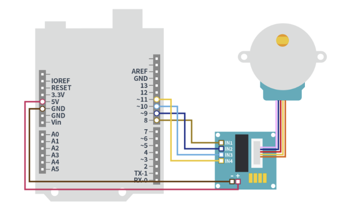
아두이노 - 스텝모터 제어
https://m.blog.naver.com/kids_power/221945072800
#include <Stepper.h>

const int stepsPerRevolution = 1024;
Stepper myStepper(stepsPerRevolution,11,9,10,8);

void setup() {
  myStepper.setSpeed(30);
  Serial.begin(9600);
}

void loop() {
    Serial.println("counterclockwise");
    myStepper.step(stepsPerRevolution*2);
    delay(1000);
}
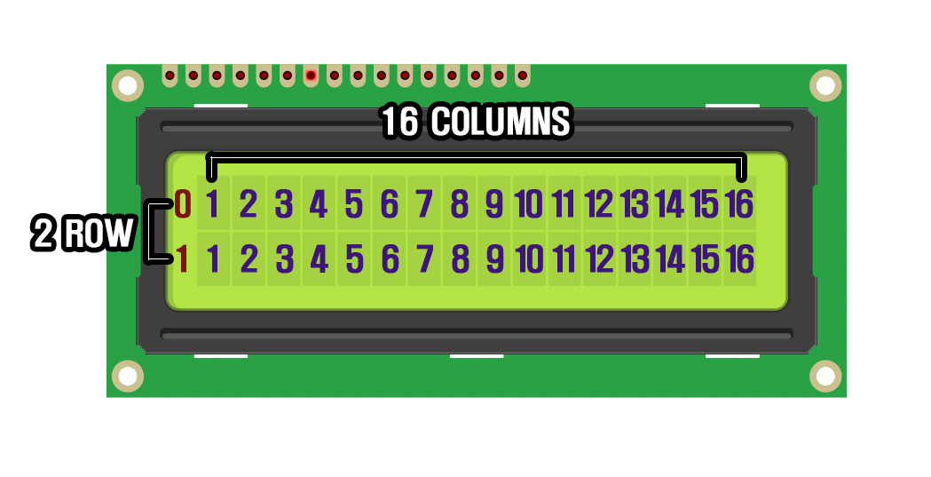
LCD
#include <Wire.h>
#include <LiquidCrystal_I2C.h>

LiquidCrystal_I2C lcd(0x27,16,2);


void setup()
{
  lcd.init();  // LCD초기 설정
  lcd.backlight(); // LCD초기 설정
  lcd.setCursor(0,0); //텍스트가 LCD에 나타날 위치
  lcd.print("Hellow, world!");
  lcd.setCursor(3,1);
  lcd.print("How are you?");
}
https://artsung410.tistory.com/47?category=951131
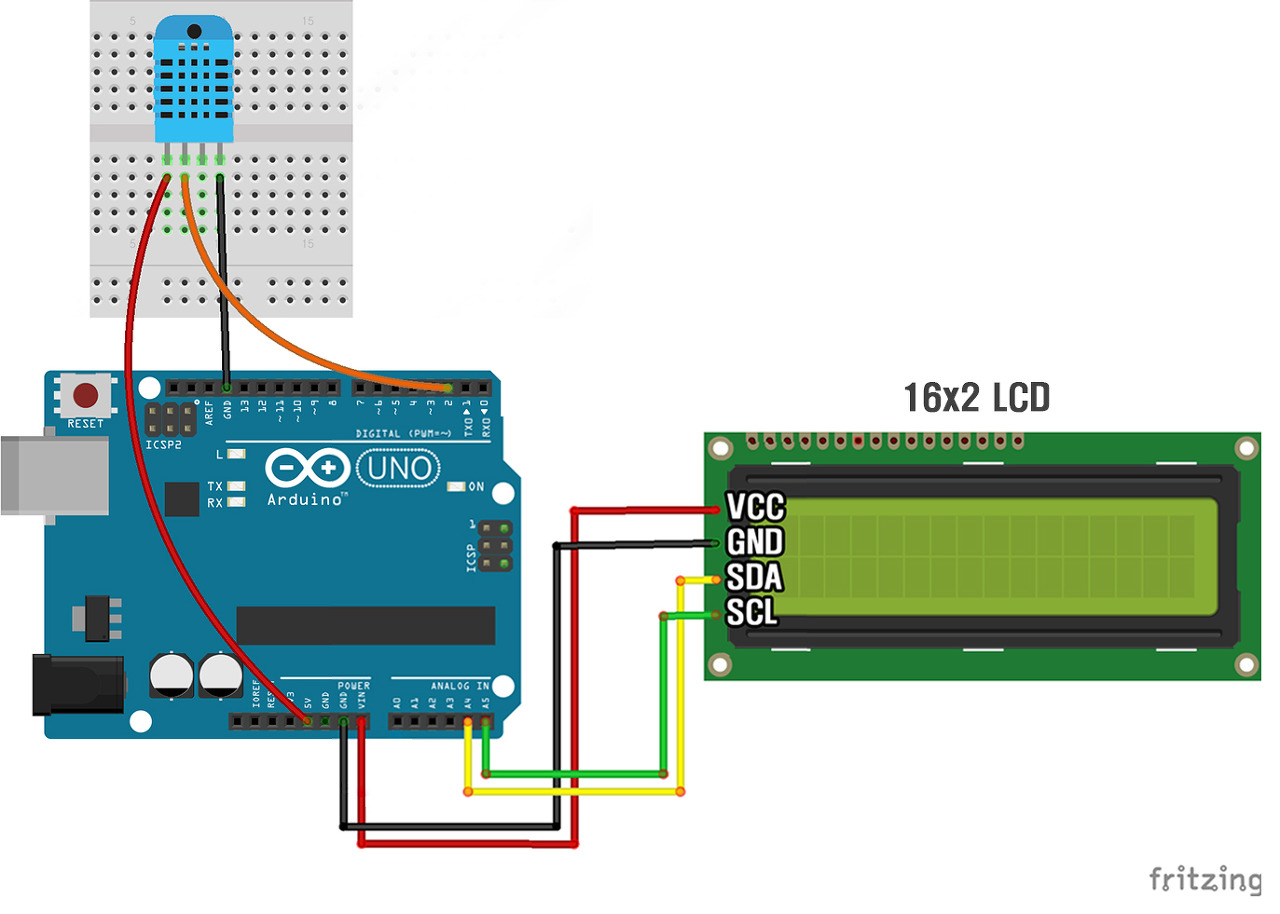
#include <Wire.h>
#include <LiquidCrystal_I2C.h>

#include <SimpleDHT.h>
LiquidCrystal_I2C lcd(0x27,16,2);

// for DHT11,
//      VCC: 5V or 3V
//      GND: GND
//      DATA: 2
int pinDHT11 = 2;
SimpleDHT11 dht11;

void setup()
{
  Serial.begin(9600);
}


void loop()
{
  lcd.init();
  byte temperature = 0;
  byte humidity = 0;
  int err = SimpleDHTErrSuccess;
  if ((err = dht11.read(pinDHT11, &temperature, &humidity, NULL)) != SimpleDHTErrSuccess) {
    Serial.print("Read DHT11 failed, err=");
    lcd.setCursor(0,0);
    lcd.print(err);
    delay(1000);
    return;
  }
  int tem = (int)temperature;
  int hum = (int)humidity;
  int index = 1.8*tem - 0.55*(1-hum / 100)*(1.8*tem - 26) + 32;
  lcd.backlight();
  lcd.setCursor(0,0);
  lcd.print("TEM : ");
  lcd.print((int)temperature);
  lcd.print("`C, ");
  lcd.print((int)humidity);
  lcd.print("H");
  lcd.setCursor(0,1);
  lcd.print("DI : ");
  lcd.print(index);
}
DC 모터 제어
아두이노 DC 모터 제어하기
[오늘의 타겟] DC 모터 / 모터 드라이버 - DC 모터 - 2개에 선에 전압을 입력하면 모터가 돌아간다. - 전압의 방향을 반대로 입력하면 모터도 반대로 돌아간다. - 참고자료 https://m.blog.naver.com/kids_power
pythonkorea.com
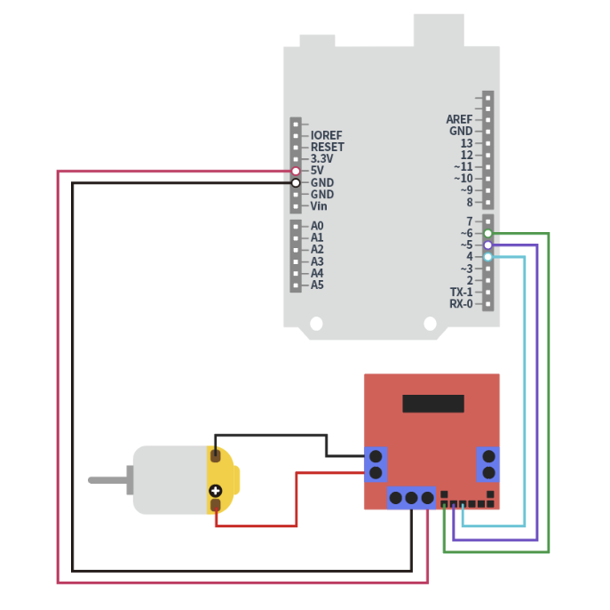
int IN1Pin = 3;
int IN2Pin = 4;
int ENPin = 5;


void setup() {
  pinMode(IN1Pin, OUTPUT);
  pinMode(IN2Pin, OUTPUT);
  analogWrite(ENPin, 80); //Max Speed
  Serial.begin(9600);
  Serial.println("start !! ");
}

void loop() {
  if(Serial.available())  //시리얼모니터에서 데이터가 들어오면
  {
    char in_data;         // 입력된 데이터 저장을 위한 변수
    in_data = Serial.read();  //입력된 데이터 in_data에 저장
     Serial.print("data : ");
     Serial.println(in_data);

    if(in_data == '1')    //입력된 데이터가 '1'이라면
    {
     digitalWrite(IN1Pin, HIGH);
     digitalWrite(IN2Pin, LOW);
    }
    else if(in_data == '2') //입력된 데이터가 '2'이라면
    {
    //뒤로 회전 (어떤 방향으로 꽂았느냐에 따라서 방향 반대)
      digitalWrite(IN1Pin, LOW);
      digitalWrite(IN2Pin, HIGH);
    }
    else if(in_data == '3') //입력된 데이터가 '3'이라면
    {
       //회전 정지
      digitalWrite(IN1Pin, HIGH);
      digitalWrite(IN2Pin, HIGH);
    }
  }
}
DC 모터 제어 - driver2
void setup() {
  pinMode(5, OUTPUT);    // 5번핀 출력모드
  pinMode(6, OUTPUT);    // 6번핀 출력모드
}

int flag = 0;


void loop() {

    if (flag == 0){
      analogWrite(5, 0);     // 5번핀 0(0V) 출력
      analogWrite(6,225);   // 6번핀 150(3V) 출력 (아두이노 Vcc 5V x 150/225)
      delay(100);
      flag = 1;
    }
    analogWrite(5, 0);     // 5번핀 0(0V) 출력
    analogWrite(6,80);   // 6번핀 150(3V) 출력 (아두이노 Vcc 5V x 150/225)
}
GPIO output
[arduino 32]
int IN1Pin = 3;
void setup() {
pinMode(IN1Pin, OUTPUT);
Serial.begin(9600);
Serial.println("start !! ");
}
void loop() {
if(Serial.available()) //시리얼모니터에서 데이터가 들어오면
{
char in_data; // 입력된 데이터 저장을 위한 변수
in_data = Serial.read(); //입력된 데이터 in_data에 저장
Serial.print("data : ");
Serial.println(in_data);
if(in_data == '1') //입력된 데이터가 '1'이라면
{
digitalWrite(IN1Pin,HIGH);
}
else if(in_data == '2') //입력된 데이터가 '2'이라면
{
digitalWrite(IN1Pin,LOW);
}
else if(in_data == '3') //입력된 데이터가 '3'이라면
{
delay(1000);
}
}
}
[ESP32]
void setup() {
  // 시리얼 통신 시작 (보레이트 설정)
  Serial.begin(115200);

  // GPIO16을 출력 모드로 설정
  pinMode(16, OUTPUT);
}

void loop() {
  // 시리얼 입력이 있는지 확인
  if (Serial.available() > 0) {
    // 시리얼 입력 읽기
    char input = Serial.read();

    // 입력 값에 따라 GPIO16 핀 제어
    if (input == '1') {
      digitalWrite(16, HIGH); // GPIO16 켜기
      Serial.println("GPIO16 ON");
    } else if (input == '2') {
      digitalWrite(16, LOW); // GPIO16 끄기
      Serial.println("GPIO16 OFF");
    }
  }
}
[ESP32]
8x8 dot matrix - arduino
나의 Dot matrix
- VCC : 주황
- GND : 빨강
- DIN : 갈색
- CS : 검정
- CLK : 흰색
#define dataIn 12 //DIN 12번 핀으로 사용
#define cs 11 //CS 11번 핀으로 사용
#define clk 10 //CLK 10번 핀으로 사용
LedControl lc = LedControl(dataIn, clk, cs, 1); //LedControl('DIN핀 번호', 'CLK핀 번호', 'CS핀 번호', 'dot matrix 갯수'
#include "LedControl.h" //dot matrix를 사용하기 위한 라이브러리 호출

#define dataIn 12   //DIN 12번 핀으로 사용
#define cs 11       //CS 11번 핀으로 사용
#define clk 10      //CLK 10번 핀으로 사용

LedControl lc = LedControl(dataIn, clk, cs, 1); //LedControl('DIN핀 번호', 'CLK핀 번호', 'CS핀 번호', 'dot matrix 갯수')

byte heart[] =
{
  B00000000,
  B01100110,
  B11111111,
  B11111111,
  B11111111,
  B01111110,
  B00111100,
  B00011000,
};

void setup() {
  lc.shutdown(0, false);
  lc.setIntensity(0, 15); // LED 도트매트릭스 밝기
  lc.clearDisplay(0); // LED 도트매트릭스 모두 지우기
}

void loop() {
  showLED(heart, 1); // 하트모양 보이기
  delay(1000); // 1초기다리기
  showLED(heart, 0); // 모두 지우기
  delay(1000); // 1초기다리기
}

// LED 도트매트릭스 제어용 함수
void showLED(byte arr[], int a)
{
  if (a == 1) {
    for (int i = 0; i < 8; i++)
    {
      lc.setRow(0, i, arr[i]);
    }
  } else {
    for (int i = 0; i < 8; i++)
    {
      lc.setRow(0, i, B00000000);
    }
  }
}
8x8 dot matrix - ESP32
ESP32와 호환되도록 LedControl 라이브러리를 사용하는 전체 코드를 제공하겠습니다. 이를 위해 LedControl.h 파일을 수정하여 avr/pgmspace.h 대신 ESP32의 pgmspace.h를 포함하도록 하겠습니다.
먼저, LedControl.h 파일에서 #include <avr/pgmspace.h>를 다음과 같이 수정합니다:
#ifdef ESP32
#include <pgmspace.h>
#else
#include <avr/pgmspace.h>
#endif
그런 다음, ESP32에서 도트 매트릭스를 제어하는 전체 코드를 작성합니다:
#include "LedControl.h" // dot matrix를 사용하기 위한 라이브러리 호출

#define dataIn 12   // DIN 12번 핀으로 사용
#define cs 13       // CS 13번 핀으로 사용
#define clk 14      // CLK 14번 핀으로 사용

LedControl lc = LedControl(dataIn, clk, cs, 1); // LedControl('DIN핀 번호', 'CLK핀 번호', 'CS핀 번호', 'dot matrix 갯수')

byte heart[] = {
  B00011100,
  B00111110,
  B01111110,
  B11111100,
  B11111100,
  B01111110,
  B00111110,
  B00011100,
};

void setup() {
  lc.shutdown(0, false);
  lc.setIntensity(0, 15); // LED 도트매트릭스 밝기
  lc.clearDisplay(0); // LED 도트매트릭스 모두 지우기
}

void loop() {
  showLED(heart, 1); // 하트모양 보이기
  delay(1000); // 1초 기다리기
  showLED(heart, 0); // 모두 지우기
  delay(1000); // 1초 기다리기
}

// LED 도트매트릭스 제어용 함수
void showLED(byte arr[], int a) {
  if (a == 1) {
    for (int i = 0; i < 8; i++) {
      lc.setRow(0, i, arr[i]);
    }
  } else {
    for (int i = 0; i < 8; i++) {
      lc.setRow(0, i, B00000000);
    }
  }
}
[주요 변경 사항 요약]
1. 헤더 파일 수정: LedControl.h 파일에서 avr/pgmspace.h 대신 ESP32용 pgmspace.h를 포함합니다.
2. 핀 번호 설정: ESP32 핀 번호를 확인하여 올바르게 설정합니다. 위의 예제에서는 dataIn을 12번, cs를 13번, clk를 14번 핀으로 설정했습니다.
3. 라이브러리 사용: ESP32와 호환되는 방식으로 LedControl 라이브러리를 사용하여 도트 매트릭스를 제어합니다.
아두이노 보드끼리 시리얼 통신
https://mkhduino.tistory.com/6
아두이노 보드끼리 시리얼 통신하기(1)
아두이노 보드끼리 uart핀을 서로 연결하여 시리얼 데이타를 주고 받을 수 있습니다. 이때 보내는 쪽 보드(TX)의 TX와 받는쪽 보드(RX)의 RX와 연결해주고, 보내는보드의 RX핀과 받는보드의 TX와 연결
mkhduino.tistory.com
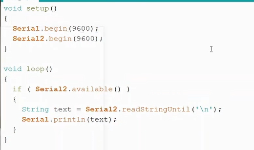
아두이노 우노와 ESP32 시리얼 통신
https://www.youtube.com/watch?app=desktop&v=wzjRDXWckqU
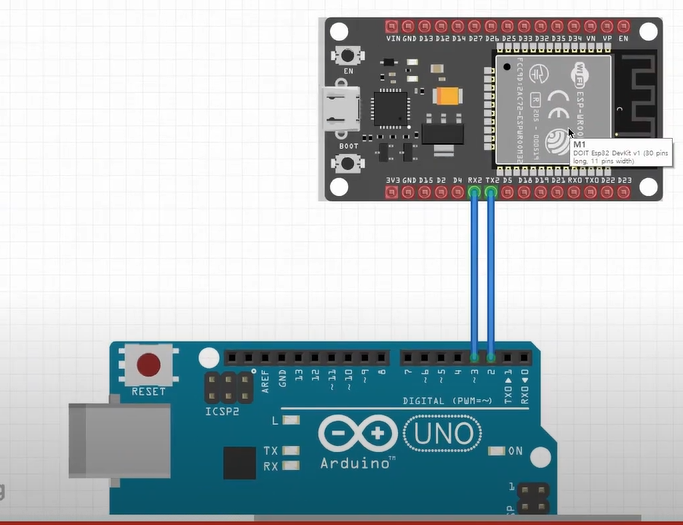
[송신 코드]
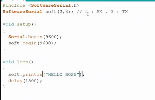
[수신 코드]
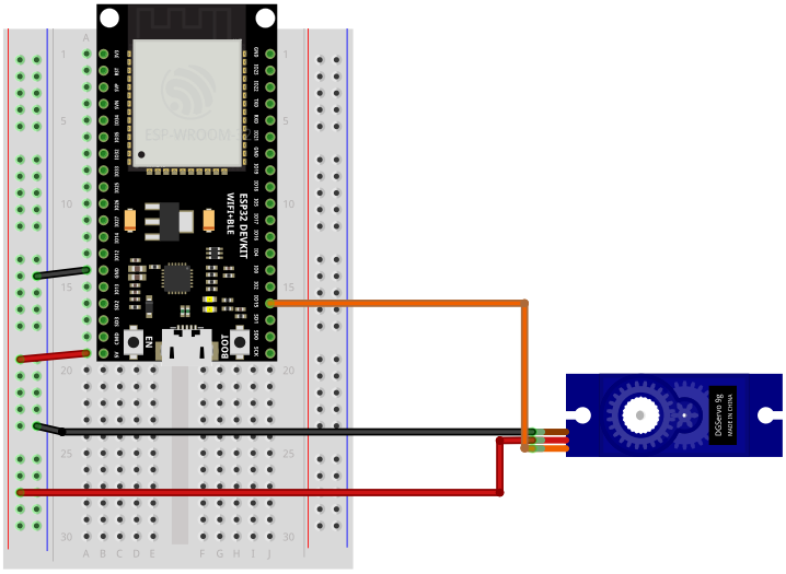
서보모터 - ESP32
https://stemwith.github.io/2020/10/19/ESP32-%EC%84%9C%EB%B3%B4%EB%AA%A8%ED%84%B0-%EC%A0%9C%EC%96%B4/
esp32 서보모터 PWM제어
SG90, MG90S, MG966R 서보모터datasheet 사용법 ESP32는 16개의 PWM채널이 있으므로, 최대 16개의 서보모터를 동시에 제어할 수 있다. 서보모터 데이터 시트의 스펙상으로는… 대부분의 서보모터(SG90, MG90S, M
stemwith.github.io
const int ledPin = 15;  // corresponds to GPIO 15

// setting PWM properties
const int ledChannel = 0;
const int freq = 50;
const int resolution = 16;
const int maxDeg = 90;

int deg, duty;

void setup()
{
  // PWM Setup
  ledcSetup(ledChannel, freq, resolution);  // PWM CH0, Frequncy 50 Hz, 16bit resolution
  ledcAttachPin(ledPin, ledChannel);        // PWM CH0을 GPIO 15번으로 출력
}

void loop()
{
  for (deg = maxDeg;deg >= 0; deg--) { //시계방향 회전
  servoWrite(ledChannel, deg);
  }
  delay(1000);
  for (deg = 0;deg <= maxDeg; deg++) { //반시계방향 회전
    servoWrite(ledChannel, deg);
  }
  delay(1000);
}

// deg는 0~180도 까지
void servoWrite(int ch, int deg)
{
    duty = map(deg, 0, 180, 1638, 8192);
    ledcWrite(ch, duty);
    delay(15);                             // delay를 줄이면 180도가 완전히 돌지 않음
}
'SSAFY > 관통 PJT' 카테고리의 다른 글
| 관통 PJT #공정코드 (4) | 2024.05.23 |
|---|---|
| 관통 PJT - visualization (0) | 2024.05.22 |
| 관통PJT #보드 코드 (0) | 2024.05.20 |
| 관통PJT #firebase, MQTT 통신 코드 (0) | 2024.05.20 |
| 관통 PJT #보드설명 (0) | 2024.05.19 |
